Ripple Voltage: Reveal Hidden Damage & Easy Solutions!
Understanding power supply performance requires careful examination of ripple voltage, a phenomenon often overlooked. Excessive ripple can significantly impact sensitive electronics. Electronic devices such as those manufactured by Texas Instruments, are particularly vulnerable. Mitigation techniques, typically involving capacitive filtering, are critical. This article delves into the intricacies of ripple voltage, providing analytical insight and offering practical solutions to minimize its detrimental effects on your power systems.
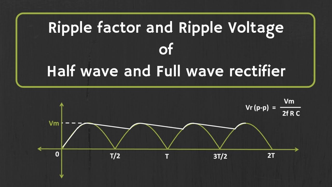
Image taken from the YouTube channel ALL ABOUT ELECTRONICS , from the video titled Calculation of Ripple Factor and Ripple Voltage for Half wave Rectifier and Full wave Rectifier .
Imagine a sophisticated medical device, its intricate circuitry meticulously designed to monitor a patient's vital signs. Now, picture it failing unexpectedly, delivering inaccurate readings at a critical moment. The culprit? Not a faulty component, but ripple voltage, a subtle yet insidious form of electrical noise.
Ripple voltage, often overlooked, poses a significant threat to the performance and longevity of electronic circuits. This article will shed light on this often-invisible phenomenon, providing practical guidance on how to identify, understand, and mitigate its harmful effects.
What is Ripple Voltage?
Ripple voltage is the residual AC voltage present on a DC power supply output. It manifests as a small, unwanted fluctuation superimposed on the desired steady DC voltage.
Think of it as tiny waves riding on an otherwise smooth surface of water. While the average voltage remains constant, these fluctuations can wreak havoc on sensitive electronic components.
The characteristics of ripple voltage are defined by its amplitude (peak-to-peak voltage), frequency, and waveform shape. These parameters depend on the design of the power supply, the components used, and the load current.
Why Does Ripple Voltage Matter?
Even small amounts of ripple voltage can cause a range of problems, from subtle performance degradation to catastrophic component failure.
-
Reduced Efficiency: Ripple voltage increases power dissipation in components, leading to reduced efficiency and increased heat generation.
-
Data Corruption: In digital circuits, ripple voltage can cause timing errors and data corruption, resulting in unreliable operation.
-
Audible Noise: In audio amplifiers, ripple voltage can manifest as unwanted hum or buzz in the output signal.
-
Component Stress: Ripple voltage can stress capacitors and other components, shortening their lifespan and increasing the risk of failure.
The Scope: Where Does Ripple Voltage Occur?
Ripple voltage is most commonly encountered in power supplies and electronic circuits. Specifically, it is prevalent in:
-
AC-DC Power Supplies: These convert AC line voltage to DC, but the rectification and filtering process inevitably introduces some ripple.
-
DC-DC Converters: These convert one DC voltage to another, and the switching action can generate significant ripple.
-
Sensitive Analog Circuits: Operational amplifiers, sensors, and other analog circuits are particularly susceptible to the effects of ripple voltage.
Essentially, any electronic device that relies on a stable DC power supply is vulnerable to the effects of ripple voltage.
Our Mission: Identifying, Understanding, and Mitigating Ripple
This article serves as a comprehensive guide to tackling the challenges posed by ripple voltage. We will explore:
-
Identification: Practical techniques for measuring and visualizing ripple voltage using an oscilloscope.
-
Understanding: The root causes of ripple voltage and the factors that influence its characteristics.
-
Mitigation: Effective strategies for reducing ripple voltage and protecting electronic circuits from its harmful effects.
By mastering these skills, engineers, technicians, and hobbyists alike can ensure the reliable and long-lasting performance of their electronic devices. We aim to empower you to tame the ripple beast and unlock the full potential of your circuits.
Understanding the Fundamentals: The Origin and Impact of Ripple
Before we can effectively combat ripple voltage, it's crucial to understand where it comes from and how it impacts our circuits. It's not enough to simply identify its presence; we need to delve into the underlying mechanisms that give rise to this pervasive form of electrical noise. This section will explore the common sources of ripple voltage, the role of capacitors in filtering, the influence of load current, and the often-overlooked impact of harmonics.
Sources of Ripple Voltage
Ripple voltage doesn't magically appear; it's a byproduct of the processes involved in converting and regulating electrical power. Understanding these sources is the first step in developing effective mitigation strategies.
Rectifiers: The AC to DC Conversion Challenge
The primary task of a rectifier is to convert alternating current (AC) into direct current (DC). However, this conversion is inherently imperfect. The output of a rectifier is not a smooth DC signal but rather a pulsating DC voltage with a significant AC component – the ripple voltage.
Depending on the rectifier configuration (half-wave, full-wave, bridge), the frequency and magnitude of this ripple will vary. Full-wave rectifiers generally produce less ripple and a higher frequency ripple than half-wave rectifiers, making them a preferable starting point for cleaner DC power. The residual ripple reflects the incomplete smoothing of the rectified AC waveform.
SMPS (Switched-Mode Power Supply): The Switching Frequency Factor
Switched-mode power supplies (SMPS) are widely used for their efficiency and compact size. However, their operation relies on high-frequency switching of transistors, which, while efficient, introduces significant noise and ripple.
The switching frequency itself becomes a major component of the ripple voltage. Higher switching frequencies can lead to smaller and more easily filtered ripple components. However, they also introduce other challenges like increased electromagnetic interference (EMI). Therefore, the choice of switching frequency represents a design trade-off.
The ripple in SMPS is further influenced by the duty cycle of the switching waveform, the characteristics of the switching transistors, and the effectiveness of the output filter.
Voltage Regulators: Persistence Despite Regulation
Voltage regulators are designed to maintain a stable output voltage despite variations in input voltage or load current. While they effectively reduce voltage fluctuations, they cannot completely eliminate ripple voltage.
Even with feedback control and sophisticated circuitry, some ripple from the input power supply can still make its way to the output. Furthermore, the regulator's internal components and control loops can themselves generate additional ripple voltage.
The Role of Capacitors: Filtering and its Limitations
Capacitors play a crucial role in filtering ripple voltage and smoothing the DC output of power supplies. They act as energy storage devices, charging during the peaks of the ripple waveform and discharging during the valleys, thereby reducing the overall ripple amplitude.
Electrolytic vs. Ceramic Capacitors
Electrolytic capacitors are commonly used for bulk filtering due to their high capacitance values. However, they have limitations in terms of ESR (Equivalent Series Resistance) and frequency response.
Ceramic capacitors, on the other hand, offer lower ESR and better high-frequency performance, making them suitable for filtering high-frequency ripple components. Combining both types of capacitors can provide effective ripple filtering across a wider frequency range.
ESR (Equivalent Series Resistance): A Limiting Factor
ESR is an inherent property of all capacitors, representing the internal resistance of the capacitor. A higher ESR results in a larger voltage drop across the capacitor when it discharges, which translates to a higher ripple voltage at the output.
Therefore, selecting capacitors with low ESR is crucial for minimizing ripple voltage, particularly at higher frequencies. Careful consideration of ESR is paramount to effective ripple filtering design.
The Impact of Load Current
The magnitude of ripple voltage is directly affected by the load current drawn from the power supply. As the load current increases, the capacitor discharges more rapidly during the ripple cycle, leading to a larger ripple voltage.
A power supply that exhibits acceptable ripple voltage at a low load current might exhibit excessive ripple at a higher load current. Therefore, it's essential to evaluate ripple voltage under realistic operating conditions and at the maximum expected load current.
Furthermore, dynamic changes in load current can introduce transient ripple components that are more difficult to filter.
How Harmonics Influence Ripple
Ripple voltage is not always a simple sinusoidal waveform. It can contain a complex mixture of harmonic frequencies, which are multiples of the fundamental ripple frequency. These harmonics arise from non-linear components and switching actions within the power supply.
The presence of harmonics can significantly alter the shape and magnitude of the ripple voltage. Higher-order harmonics can introduce sharp spikes and ringing in the ripple waveform, which can be particularly problematic for sensitive electronic circuits.
Analyzing the harmonic content of ripple voltage can provide valuable insights into the source of the ripple and guide the selection of appropriate filtering techniques. Spectrum analyzers and Fourier analysis tools can be used to identify and quantify the harmonic components present in the ripple waveform.
The journey to understanding ripple voltage's origins and its effects on circuit behavior provides a solid theoretical foundation. However, theory alone is insufficient. We must now translate this knowledge into practical skills, learning to identify and quantify ripple voltage in real-world circuits. This is where the oscilloscope becomes an indispensable tool, allowing us to "see" the unseen and diagnose potential problems with precision.
Identifying Ripple Voltage: Diagnosis and Measurement Techniques
The oscilloscope is the cornerstone of ripple voltage diagnosis. Its ability to visualize electrical signals over time allows us to identify the presence, amplitude, and frequency of ripple, providing critical data for troubleshooting and mitigation. Mastering its use is essential for any electronics professional or enthusiast.
Using an Oscilloscope for Ripple Measurement
The oscilloscope, with its ability to display voltage variations over time, is the primary instrument for identifying and measuring ripple voltage. However, achieving accurate and meaningful measurements requires a careful setup and a thorough understanding of the instrument's controls.
Setting up the Oscilloscope
Proper oscilloscope setup is crucial for accurate ripple measurement. Start by selecting the correct probe. A 1x probe is often suitable for low-voltage circuits, while a 10x probe can be used to reduce circuit loading and improve signal fidelity, especially at higher frequencies.
Next, select the appropriate voltage scale (volts/division) to maximize the display's vertical resolution without clipping the waveform. For ripple measurements, AC coupling is essential, as it blocks the DC component of the signal, allowing you to focus on the ripple itself.
Finally, adjust the time base (seconds/division) to display several cycles of the ripple waveform. Triggering should be set to a stable edge of the ripple signal, ensuring a clear and consistent display. Grounding is paramount; always use a short ground lead to minimize ground loop inductance and noise pickup.
Interpreting the Waveform
The oscilloscope display provides a wealth of information about the ripple voltage. The vertical axis represents the voltage, while the horizontal axis represents time. The waveform's amplitude indicates the magnitude of the ripple, while its frequency indicates how often the ripple repeats.
The shape of the waveform can also provide valuable clues. A sawtooth waveform, for example, might indicate a capacitor charging and discharging, while a more complex waveform could suggest the presence of harmonics or other noise sources.
Key Parameters to Observe
Once the oscilloscope is set up and the waveform is displayed, the next step is to identify and measure the key parameters that characterize the ripple voltage. These parameters provide quantifiable data that can be used to assess the severity of the ripple and guide mitigation efforts.
Peak-to-Peak Ripple Voltage
The peak-to-peak ripple voltage (Vp-p) is the difference between the maximum and minimum voltage levels of the ripple waveform. This is arguably the most important parameter, as it directly indicates the magnitude of the voltage fluctuations. A high Vp-p value suggests a significant amount of ripple, which could potentially cause problems for sensitive electronic components.
Frequency of the Ripple
The frequency of the ripple voltage corresponds to how often the ripple pattern repeats itself. In rectifier circuits, the ripple frequency is typically a multiple of the AC line frequency (e.g., 60 Hz in the US). In SMPS, the ripple frequency is usually related to the switching frequency.
Knowing the ripple frequency can help identify the source of the ripple and guide the selection of appropriate filtering components. For instance, a low-frequency ripple might be effectively filtered with a large electrolytic capacitor, while a high-frequency ripple might require a ceramic capacitor with low equivalent series inductance (ESL).
Case Studies in Ripple Voltage Diagnosis
The principles discussed above can be best illustrated through real-world examples. Let’s consider a couple of scenarios:
Case Study 1: Audio Amplifier Hum
An audio amplifier exhibits a noticeable hum. Using an oscilloscope, a 120 Hz ripple voltage is observed on the power supply rail. This indicates inadequate filtering after rectification of the AC line voltage. The solution involves increasing the capacitance of the filter capacitor or improving its ESR characteristics.
Case Study 2: Microcontroller Malfunction
A microcontroller intermittently malfunctions. Oscilloscope probing reveals high-frequency ripple on the VCC line, likely originating from the switching regulator. Adding a ceramic bypass capacitor close to the microcontroller's power pins helps to decouple the noise and stabilize the voltage.
These case studies underscore the importance of understanding and addressing ripple voltage issues. By employing the techniques outlined above, engineers and technicians can effectively diagnose and mitigate ripple voltage problems, ensuring the reliable operation of electronic circuits.
The oscilloscope has shown us the problem – the telltale ripple voltage corrupting our otherwise clean DC power. But detection is only half the battle. Now, we must turn our attention to the solutions, the strategies, and techniques that allow us to tame this ripple beast and restore stability to our circuits.
Solutions and Mitigation Strategies: Taming the Ripple Beast
Effective ripple voltage mitigation requires a multifaceted approach, considering the source of the ripple, the sensitivity of the affected circuitry, and the overall system design. We'll explore techniques ranging from component selection to circuit design modifications, providing you with a comprehensive toolkit for ripple reduction.
Optimizing Capacitor Selection
Capacitors are the first line of defense against ripple voltage. Choosing the right capacitor, however, is more than just picking a value off the shelf. It's about understanding the nuances of different capacitor types and their behavior under specific operating conditions.
Selecting the Right Type and Value
Electrolytic capacitors are commonly used for bulk filtering due to their high capacitance values. However, their Equivalent Series Resistance (ESR) can limit their effectiveness at higher frequencies. Ceramic capacitors, on the other hand, offer low ESR but typically have lower capacitance values.
The key is to select a capacitor with the appropriate capacitance and ESR for the frequency range of the ripple you're trying to attenuate. Sometimes, paralleling different types of capacitors can provide the best of both worlds – high capacitance for low-frequency ripple and low ESR for high-frequency components.
Temperature and Lifespan Considerations
Capacitor performance degrades with temperature and age. Electrolytic capacitors, in particular, have a limited lifespan and their capacitance and ESR can change significantly over time, especially at elevated temperatures.
Therefore, it's crucial to select capacitors that are rated for the expected operating temperature range and to consider their lifespan when designing for long-term reliability. Using high-quality, low-ESR capacitors rated for high temperatures can significantly improve filtering performance and extend the lifespan of your circuits.
Implementing Filters
While capacitors provide a basic level of filtering, more complex filter circuits can offer significantly improved ripple attenuation. LC and RC filters are two common types of filters used for ripple reduction.
LC Filters: Design Considerations and Applications
LC filters, consisting of an inductor (L) and a capacitor (C), offer excellent ripple attenuation due to their ability to create a resonant circuit that blocks a specific frequency range. These filters are particularly effective at attenuating ripple at the switching frequency of SMPS.
Designing an LC filter involves selecting the appropriate inductance and capacitance values to achieve the desired cutoff frequency and attenuation characteristics. Inductors, however, can be bulky and expensive, so their use is often reserved for applications where high ripple attenuation is required.
RC Filters: Simpler Solutions for Lower-Frequency Ripple
RC filters, consisting of a resistor (R) and a capacitor (C), are simpler and more cost-effective than LC filters. They are typically used for attenuating lower-frequency ripple components.
The effectiveness of an RC filter is limited by the resistor's impedance, which can reduce the filter's ability to attenuate ripple. However, for applications where the ripple frequency is relatively low and high attenuation is not required, RC filters can provide a simple and effective solution.
Improving Voltage Regulator Performance
Voltage regulators are designed to provide a stable output voltage, but they can also contribute to ripple voltage if not properly designed or selected.
Selecting Low-Noise Voltage Regulators
Some voltage regulators are inherently noisier than others. Selecting a low-noise voltage regulator can significantly reduce the amount of ripple present on the output voltage.
Look for regulators with low output noise specifications and consider using linear regulators instead of switching regulators in noise-sensitive applications. While linear regulators are less efficient, they typically produce less ripple voltage.
Optimizing Feedback Loop Design
The feedback loop in a voltage regulator plays a critical role in maintaining a stable output voltage. However, a poorly designed feedback loop can actually amplify ripple voltage.
Optimizing the feedback loop involves carefully selecting the compensation components to ensure that the loop is stable and has sufficient bandwidth to suppress ripple voltage. Proper compensation can significantly improve the regulator's ability to reject ripple and maintain a stable output voltage.
Reducing Switching Noise in SMPS
Switched-Mode Power Supplies (SMPS) are notorious for generating ripple voltage due to the rapid switching of current. Reducing switching noise is essential for minimizing ripple in SMPS circuits.
Optimizing Switching Frequency
The switching frequency of an SMPS directly affects the frequency of the ripple voltage. Increasing the switching frequency can reduce the amplitude of the ripple, but it can also increase switching losses and electromagnetic interference (EMI).
Therefore, optimizing the switching frequency involves finding a balance between ripple amplitude, switching losses, and EMI. Some SMPS controllers offer features such as frequency dithering, which can spread the ripple energy over a wider frequency range, reducing the peak amplitude.
Shielding and Grounding Techniques
Proper shielding and grounding are essential for reducing switching noise in SMPS circuits. Shielding involves enclosing the SMPS components in a conductive enclosure to prevent electromagnetic radiation.
Grounding involves creating a low-impedance path for current to flow back to the power source. Using a ground plane and star grounding techniques can minimize ground loops and reduce noise coupling.
Improving Stability to Minimize Ripple Voltage Issues
A stable power supply is less susceptible to ripple voltage. Instabilities can amplify existing ripple or even generate new ripple components.
Ensuring adequate phase margin in feedback loops, using decoupling capacitors near sensitive components, and properly terminating transmission lines can all contribute to a more stable and less ripple-prone system. Thorough testing and analysis, including Bode plots and transient response measurements, can help identify and address potential stability issues before they manifest as excessive ripple voltage.
The solutions we've explored provide powerful tools for addressing ripple voltage when it arises. However, the most effective strategy is to prevent ripple from becoming a problem in the first place. This proactive approach, encompassing careful design practices, diligent maintenance, and informed component selection, can significantly reduce the risk of ripple-related issues and ensure the long-term reliability of electronic systems.
Preventing Ripple Voltage: Proactive Design and Maintenance
Prevention, in the realm of electronics, is undeniably better than cure. Addressing ripple voltage reactively, while necessary at times, can be resource-intensive and disruptive. A forward-thinking approach, integrating preventative measures from the outset, offers a far more efficient and cost-effective path to robust and reliable circuits. Let's examine the key pillars of ripple voltage prevention: design best practices, diligent maintenance, and informed power supply selection.
Best Practices in Electronic Circuit Design
Effective circuit design considers ripple voltage mitigation from the initial stages. Thoughtful grounding, strategic shielding, and optimized component placement are not merely good habits; they are essential defenses against unwanted noise and ripple.
-
Grounding Techniques: A well-designed grounding system is crucial. Implement a star grounding configuration to minimize ground loops, which can introduce noise and contribute to ripple voltage. Ensure low-impedance ground connections to prevent voltage drops and maintain a stable reference. Proper grounding is not an afterthought; it's a fundamental aspect of a clean and stable power supply.
-
Shielding Strategies: Shielding is another powerful tool in the fight against ripple. Enclose sensitive components in grounded metal enclosures to block electromagnetic interference (EMI). Use shielded cables to prevent noise from coupling into signal lines. Consider the frequencies of potential noise sources when selecting shielding materials, as different materials offer varying levels of effectiveness at different frequencies.
-
Component Placement: The physical layout of components can significantly impact ripple voltage. Place decoupling capacitors close to the power pins of integrated circuits (ICs) to provide a local source of clean power. Keep high-frequency switching components away from sensitive analog circuitry to minimize noise coupling. A compact and well-organized layout minimizes parasitic inductances and capacitances that can exacerbate ripple problems.
Regular Maintenance and Testing
Even with the best design practices, periodic checks are essential. Ripple voltage can increase over time due to component aging, changes in operating conditions, or the introduction of new noise sources.
-
Periodic Ripple Voltage Checks: Implement a schedule for regular ripple voltage measurements. Use an oscilloscope to monitor ripple levels at critical points in the circuit. Establish baseline measurements and track changes over time. Any significant increase in ripple voltage should be investigated promptly to identify the underlying cause.
-
Component Inspection: Regular visual inspection of components can reveal potential problems before they lead to significant ripple issues. Look for signs of overheating, bulging capacitors, or damaged insulation. Replace any suspect components proactively to prevent failures and maintain optimal performance.
-
Environmental Considerations: Consider the operating environment when planning maintenance. High temperatures, humidity, and vibration can accelerate component degradation and increase the risk of ripple-related problems. Adjust maintenance schedules accordingly to account for these factors.
The Importance of Power Supply Selection
The power supply is the heart of any electronic system, and its quality directly impacts ripple voltage. Choosing a power supply with low ripple specifications is a crucial step in preventing ripple-related problems.
-
Understanding Ripple Specifications: Carefully review the power supply's datasheet and pay close attention to the ripple voltage specification. Ensure that the specified ripple voltage is acceptable for the most sensitive components in your circuit.
-
Testing and Validation: Don't rely solely on the manufacturer's specifications. Independently test the power supply's ripple voltage under various load conditions to verify its performance. Use an oscilloscope to measure ripple voltage at the output of the power supply and at critical points in your circuit.
-
Consider Reputable Manufacturers: Choose power supplies from reputable manufacturers with a track record of producing high-quality, low-ripple devices. Read reviews and seek recommendations from other engineers to ensure that you are selecting a reliable power supply.
Video: Ripple Voltage: Reveal Hidden Damage & Easy Solutions!

Ripple Voltage: FAQs About Hidden Damage and Solutions
Here are some frequently asked questions about ripple voltage, its causes, effects, and solutions, to help you better understand this important aspect of power electronics.
What exactly is ripple voltage?
Ripple voltage is the small AC component that remains on top of a DC voltage after rectification. Ideally, a DC power supply should output a perfectly smooth, constant voltage. However, due to imperfections in the filtering process, a small amount of AC voltage, the ripple voltage, is always present.
How does ripple voltage cause damage?
Excessive ripple voltage can lead to various issues. It generates extra heat in components, stressing them and reducing their lifespan. It can also cause erratic behavior in sensitive circuits, leading to inaccurate readings or malfunctions. High ripple voltage puts a strain on capacitors in particular.
What are some common sources of ripple voltage?
Common causes include insufficient capacitance in the filter capacitor, a failing filter capacitor, or issues with the rectifier diodes. The switching frequency of a power supply can also contribute to ripple voltage. Even excessive load current can increase ripple.
What can I do to reduce ripple voltage?
Increasing the capacitance of the filter capacitor is a common solution. Also, checking and replacing any failing components, like rectifier diodes or damaged capacitors, can significantly reduce ripple voltage. Implementing better filtering techniques in the power supply design also helps minimize ripple.