Current Symbol: A Comprehensive Guide to Using It
The current symbol (I) plays a pivotal role in electrical engineering. The Institute of Electrical and Electronics Engineers (IEEE) standardizes the notation for electrical quantities. The ammeter is the instrument used to measure electrical current in amperes (A). Proper comprehension and application of the current symbol is necessary when applying Ohm's Law.
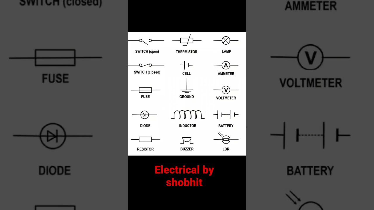
Image taken from the YouTube channel electrical by shobhit , from the video titled electrical symbols .
Unveiling the Mysteries of Electric Current
Electric current stands as a fundamental cornerstone of electrical science, permeating every facet of our technologically advanced world. From the intricate circuits powering our smartphones to the vast networks distributing energy across continents, electric current underpins modern civilization.
Defining Electric Current
At its core, electric current is defined as the flow of electric charge. This flow, typically carried by electrons within a conductor, is quantified by the amount of charge passing through a given point per unit of time. This movement of charge is responsible for a wide array of electrical phenomena.
The Ubiquitous Nature of Electric Current
Electric current's presence is so pervasive that it often goes unnoticed. Yet, it is the lifeblood of countless applications.
- Electronics: Powering microchips and enabling complex computations.
- Power Systems: Transporting energy from power plants to homes and industries.
- Transportation: Driving electric vehicles and powering onboard systems in conventional vehicles.
- Medical Devices: Enabling life-saving diagnostics and treatments.
This brief list is not exhaustive, but it serves to illustrate the indispensable role of electric current in our daily lives.
Objectives of this Discourse
This discourse aims to demystify electric current, providing a comprehensive understanding of its underlying principles. We will explore the fundamental concepts that govern its behavior, the diverse methods employed for its measurement, and its far-reaching applications across various fields.
By the end of this exploration, readers will possess a solid foundation in the theory and practical aspects of electric current, empowering them to appreciate its significance and enabling informed engagement with electrical technologies.
Fundamental Concepts: Delving into the Nature of Electric Current
Unveiling the foundational principles governing electric current is essential for comprehending its behavior and applications. This section serves as a primer, establishing a clear understanding of electric current itself and the key factors that dictate its magnitude and direction within electrical circuits. We will explore the concept of electromotive force, the nature of resistance, and the unifying relationship described by Ohm's Law.
Defining Electric Current: The Flow of Charge
Electric current, at its core, is defined as the ordered flow of electric charge. In most conductive materials, this charge is carried by electrons. However, it's crucial to understand that current is not simply the presence of electrons; it's their directed motion.
The quantity of charge (Q) passing a given point in a circuit per unit of time (t) determines the magnitude of the current (I). This relationship is expressed mathematically as:
I = Q/t
Where current (I) is measured in Amperes (A), charge (Q) is measured in Coulombs (C), and time (t) is measured in seconds (s). The implications of this definition are profound. It highlights the dynamic nature of current and its direct dependence on the movement of charge.
Electromotive Force (EMF): The Driving Force Behind Current
While the presence of charge carriers is necessary for current flow, it is not sufficient. A driving force is required to compel these charges to move. This force is known as electromotive force (EMF).
EMF is the energy per unit charge available to drive electric current through a circuit. It is often mistakenly conflated with voltage (V). However, EMF represents the source of electrical potential difference, while voltage is the potential difference measured across circuit elements. Think of EMF as the push, and voltage as the resulting difference in electrical "height".
Resistance (R): Impeding the Flow
Resistance (R) is the inherent property of a material to oppose the flow of electric current. All materials exhibit some degree of resistance, from highly conductive metals to insulating materials.
Several factors influence a material's resistance. These include:
- Material: Different materials possess varying atomic structures and electron mobility, leading to different resistance levels.
- Temperature: In most conductors, resistance increases with temperature due to increased atomic vibrations hindering electron flow.
- Length and Cross-sectional Area: Longer conductors offer greater resistance, while conductors with larger cross-sectional areas offer less resistance.
Understanding resistance is critical because it dictates how much current will flow for a given applied voltage.
Ohm's Law: Quantifying the Relationship
Ohm's Law provides a fundamental relationship between voltage (V), current (I), and resistance (R) in a circuit. It states that the voltage across a conductor is directly proportional to the current flowing through it, with the constant of proportionality being the resistance.
Mathematically, Ohm's Law is expressed as:
V = IR
This simple equation is a cornerstone of circuit analysis. It allows engineers and technicians to calculate current, voltage, or resistance if the other two values are known.
Applications and Limitations of Ohm's Law
Ohm's Law is extensively used in circuit design, troubleshooting, and analysis. It is an essential tool for predicting circuit behavior and ensuring proper operation.
However, it's crucial to acknowledge that Ohm's Law has limitations. It applies primarily to linear, ohmic resistors, where resistance remains constant regardless of voltage or current. Certain components, like diodes and transistors, exhibit non-linear behavior and do not strictly adhere to Ohm's Law. Furthermore, Ohm's Law does not account for temperature effects or the behavior of AC circuits with reactive components (capacitors and inductors).
Direction of Current: Conventional vs. Electron Flow
A historical convention dictates the described direction of electric current as flowing from positive to negative. This is known as conventional current.
However, in reality, electrons (which carry a negative charge) are the primary charge carriers in most conductors. Therefore, electrons actually flow from negative to positive. This is termed electron flow.
While electron flow provides a more accurate representation of charge movement, conventional current remains the standard for circuit analysis and most electrical engineering practices. This is because the mathematical equations and circuit laws were established based on the conventional current direction. Maintaining this convention ensures consistency and avoids confusion.
Types of Electric Current: DC, AC, and Beyond
Understanding the nature of electric current extends beyond the basic principles; it requires a differentiation of its various forms. Electric current manifests primarily as Direct Current (DC) and Alternating Current (AC), each possessing distinct characteristics and applications. Furthermore, a comprehensive understanding necessitates acknowledging anomalous currents that can pose operational and safety challenges.
Direct Current (DC): The Realm of Unidirectional Flow
Direct Current (DC) is characterized by its unidirectional flow of electric charge.
Electrons move consistently in one direction, creating a steady and stable current.
This consistent flow distinguishes DC from other forms of current, making it ideal for applications demanding stable power.
Applications of DC Current
DC finds widespread use in electronics, powering devices ranging from smartphones to computers.
Its stable current is crucial for the reliable operation of integrated circuits and other sensitive electronic components.
Additionally, DC is prevalent in low-voltage systems, such as those found in automotive applications and portable devices.
The consistent voltage provided by DC sources is essential for these applications.
Alternating Current (AC): The Dance of Periodic Reversal
Alternating Current (AC) is defined by its periodic reversal of current direction.
Unlike DC, where electrons flow in a single direction, AC sees electrons oscillate back and forth, creating a sinusoidal waveform.
This periodic change in direction is a defining characteristic of AC.
Applications of AC Current
AC is the backbone of power transmission, enabling the efficient distribution of electricity over long distances.
The ability to easily transform voltage levels using transformers makes AC ideal for high-voltage transmission and low-voltage distribution.
Furthermore, AC is the standard for household electricity, powering appliances and lighting in homes and businesses.
Its widespread availability and compatibility with various electrical devices make AC a ubiquitous power source.
Quantifying AC Current: RMS, Instantaneous, and Average
Quantifying AC current requires considering parameters beyond a simple magnitude, due to its constantly changing nature. Root Mean Square (RMS), instantaneous, and average values provide different perspectives on AC current.
RMS Current: The Effective Value
The RMS (Root Mean Square) current represents the effective value of an AC current.
It is the DC equivalent that would produce the same heating effect in a resistive load.
RMS current is crucial for calculating power dissipation and ensuring proper sizing of electrical components.
Instantaneous Current: A Snapshot in Time
Instantaneous current refers to the value of AC current at a specific point in time.
It varies continuously according to the sinusoidal waveform.
While instantaneous values are useful for analyzing AC waveforms, they are less practical for power calculations.
Average Current: A Limited Perspective
Average current represents the mean value of AC current over a complete cycle.
For a purely sinusoidal waveform, the average current is zero, as the positive and negative halves cancel each other out.
The average current is not typically used for AC power calculations.
Anomalous Currents: Unveiling Deviations from the Norm
Beyond the standard DC and AC currents, several anomalous currents can arise in electrical systems, posing potential hazards and operational disruptions.
These include leakage, fault, and inrush currents, each with distinct causes and consequences.
Leakage Current: The Subtle Drain
Leakage current refers to the small current that flows through unintended paths, such as insulation or parasitic capacitances.
It arises due to imperfections in insulation materials or the presence of conductive contaminants.
Excessive leakage current can lead to energy losses, equipment malfunction, and even electrical shock hazards.
Fault Current: The Peril of Short Circuits
Fault current is the high current that results from a short circuit, where an unintended low-resistance path is created.
This can occur due to insulation failure, accidental contact, or equipment malfunction.
Fault currents can rapidly escalate, causing damage to equipment, fire hazards, and posing significant safety risks.
Protective devices, such as circuit breakers and fuses, are crucial for interrupting fault currents and preventing catastrophic consequences.
Inrush Current: The Startup Surge
Inrush current refers to the high instantaneous current drawn by electrical devices upon startup.
This is common in devices with capacitive or inductive loads, such as motors, transformers, and power supplies.
Inrush currents can be several times higher than the steady-state operating current, potentially causing nuisance tripping of circuit breakers or damaging components. Mitigation strategies include using soft starters or current-limiting devices.
Measuring Electric Current: Tools and Techniques
Understanding and manipulating electric current requires precise measurement, and the tools for this purpose have evolved significantly over time. This section details the fundamental unit of measurement for electric current, the array of instruments used to quantify it, and the underlying principles that govern their operation. From basic ammeters to advanced oscilloscopes, each tool offers a unique perspective on electrical behavior, enabling engineers and technicians to diagnose, analyze, and optimize electrical systems with confidence.
The Ampere (A): Defining the Unit of Electric Current
The Ampere, symbolized as 'A', is the SI unit of electric current, named in honor of André-Marie Ampère for his pioneering work in electromagnetism. One Ampere is defined as the constant current which, if maintained in two straight parallel conductors of infinite length, of negligible circular cross-section, and placed one meter apart in vacuum, would produce between these conductors a force equal to 2 × 10⁻⁷ newtons per meter of length. This definition provides a precise and reproducible standard for quantifying electric current.
Relationship to Other Electrical Units
The Ampere is intricately linked to other fundamental electrical units.
-
Voltage (Volt): The Ampere is related to the Volt through Ohm's Law (V = IR), where voltage is the product of current and resistance. A higher voltage can drive a larger current through a given resistance.
-
Resistance (Ohm): Resistance, measured in Ohms, limits the amount of current that flows for a given voltage. The Ampere is inversely proportional to the Ohm when the voltage is constant.
-
Power (Watt): Electrical power, measured in Watts, is the product of voltage and current (P = VI). The Ampere directly influences the power delivered in an electrical circuit.
Instrumentation: A Range of Measurement Tools
Measuring electric current involves a variety of instruments, each suited to specific applications and measurement requirements.
The choice of instrument depends on factors such as the type of current (AC or DC), the magnitude of the current, and the desired level of precision.
Ammeters: Measuring Current Directly
An ammeter is an instrument used to measure electric current directly in a circuit. It must be connected in series with the circuit so that the current being measured flows through the ammeter.
Ideally, an ammeter should have very low internal resistance to minimize its impact on the circuit's current.
Modern ammeters often use shunt resistors, where a small, known resistance is placed in parallel with a sensitive meter. The voltage drop across the shunt is proportional to the current, allowing the meter to display the current value accurately.
Multimeters: Versatile Measurement Devices
A multimeter is a versatile instrument capable of measuring voltage, current, and resistance. It combines the functionalities of an ammeter, voltmeter, and ohmmeter into a single device. Multimeters are indispensable tools for electrical troubleshooting, circuit testing, and general electrical measurements. They are available in both analog and digital versions, with digital multimeters (DMMs) providing higher accuracy and easier readability.
Oscilloscopes: Visualizing Current Waveforms
An oscilloscope is an instrument that displays the waveform of an electrical signal as a function of time. While primarily used to measure voltage, an oscilloscope can also measure current by measuring the voltage across a known resistance in the circuit. The waveform provides valuable information about the signal's amplitude, frequency, and shape, enabling detailed analysis of complex electrical signals.
Oscilloscopes are essential for diagnosing signal distortions, noise, and other anomalies in electronic circuits.
Current Transformers (CTs): Measuring High Currents Safely
A current transformer (CT) is a type of transformer used to measure alternating current (AC). It produces a current in its secondary winding, which is proportional to the current in its primary winding. CTs are used to safely measure high currents without directly connecting the measuring instrument to the high-current circuit. This isolation is crucial in high-power applications to protect both the equipment and the operator.
Clamp Meters: Non-Invasive Current Measurement
A clamp meter is a type of ammeter that measures current without needing to make physical contact with the conductor. It uses a clamp that can be opened and closed around a wire to measure the magnetic field produced by the current flowing through the wire. Clamp meters are particularly useful for measuring current in situations where it is not possible or safe to interrupt the circuit to insert a traditional ammeter.
Tools and Devices: Power Supplies and Function Generators
Beyond measurement, manipulating electric current often involves specialized tools such as power supplies and function generators.
Power Supplies: Providing Controlled Current and Voltage
A power supply is a device that provides a stable and controlled source of electrical power. Power supplies can be designed to deliver either DC or AC voltage, and they often include features such as voltage and current limiting to protect the connected circuit from damage. Adjustable power supplies allow users to vary the voltage and current output, enabling them to test and experiment with different circuit configurations.
Function Generators: Generating Specific Electrical Waveforms
A function generator is an electronic instrument that produces various types of electrical waveforms, such as sine waves, square waves, triangle waves, and pulse waves. These waveforms can be used to test the response of electronic circuits to different types of signals. Function generators allow users to adjust the frequency, amplitude, and offset of the generated waveforms, providing a flexible tool for circuit analysis and design.
Key Figures: Pioneers of Electric Current Theory
Measuring Electric Current: Tools and Techniques Understanding and manipulating electric current requires precise measurement, and the tools for this purpose have evolved significantly over time. Now, to truly grasp the field of electric current, it’s essential to acknowledge the brilliant minds who laid its foundations. This section delves into the pivotal contributions of André-Marie Ampère and Georg Ohm, two giants whose insights shaped our understanding of electricity.
André-Marie Ampère: The Electromagnetism Pioneer
André-Marie Ampère (1775-1836) stands as a towering figure in the history of electromagnetism. His meticulous experiments and profound theoretical insights provided the framework for understanding the relationship between electricity and magnetism.
Ampère’s work wasn't just about discovering isolated phenomena; it was about synthesizing a unified view.
Ampère's Contributions to Electromagnetism
Ampère's most significant contribution was his discovery that two parallel wires carrying electric currents exert a force on each other. He meticulously studied these forces, observing that parallel currents attract, while anti-parallel currents repel.
These observations led him to formulate a mathematical law describing the force between current-carrying wires, now known as Ampère's force law.
Ampère also introduced the concept of electrodynamics, the study of the forces between moving electric charges. This paved the way for a deeper understanding of electromagnetic phenomena.
Defining the Ampere
In recognition of Ampère's fundamental contributions, the SI unit of electric current was named the Ampere (A). This unit is defined based on the force between two parallel wires carrying equal currents. Specifically, it is the constant current which, if maintained in two straight parallel conductors of infinite length, of negligible circular cross-section, and placed 1 meter apart in vacuum, would produce between these conductors a force equal to 2 × 10⁻⁷ newtons per meter of length.
This definition underscores the enduring importance of Ampère's work in establishing a quantifiable measure for electric current.
Ampère's Law
Ampère’s Circuital Law states that the integral of magnetic field intensity around any closed path is equal to the current enclosed by that path. Mathematically, it's represented as ∮ B ⋅ dl = μ₀I, where B is the magnetic field, dl is an infinitesimal length element, μ₀ is the permeability of free space, and I is the current.
This law provides a powerful tool for calculating magnetic fields generated by current distributions, and forms one of the fundamental equations of electromagnetism. It links current directly to the magnetic fields it creates.
Georg Ohm: The Lawmaker
Georg Simon Ohm (1789-1854) was a German physicist who made groundbreaking contributions to the understanding of electrical resistance. His meticulous experiments and mathematical analysis led to the formulation of Ohm's Law, a cornerstone of circuit theory.
Ohm's Formulation of Ohm's Law
Ohm's Law states that the current through a conductor between two points is directly proportional to the voltage across the two points, and inversely proportional to the resistance of the conductor.
Mathematically, it is expressed as V = IR, where V is the voltage, I is the current, and R is the resistance.
Ohm's Law provides a simple yet powerful relationship between these three fundamental quantities, allowing engineers and scientists to analyze and design electrical circuits.
Impact on Circuit Analysis
Ohm’s Law revolutionized circuit analysis by providing a quantitative tool to predict and understand circuit behavior.
Before Ohm's Law, circuit design was largely empirical, relying on trial and error.
Ohm's Law allowed for the systematic analysis of circuits, enabling engineers to calculate currents, voltages, and resistances with precision.
This greatly facilitated the design of complex electrical systems, paving the way for the development of modern electronics and electrical engineering. Ohm’s Law, despite its simplicity, remains an indispensable tool for anyone working with electrical circuits.
Key Figures: Pioneers of Electric Current Theory Measuring Electric Current: Tools and Techniques
Understanding and manipulating electric current requires precise measurement, and the tools for this purpose have evolved significantly over time. Now, to truly grasp the field of electric current, it’s essential to acknowledge the brilliant minds who...
Applications and Related Fields: The Impact of Electric Current
Electric current isn't just a theoretical concept confined to textbooks; it is the lifeblood of numerous fields that shape our modern world.
From powering our homes to enabling sophisticated electronics, its applications are vast and continuously evolving.
This section delves into the practical manifestations of electric current across key domains, highlighting its indispensable role in driving technological advancements and societal progress.
Electrical Engineering: Powering the World
At its core, electrical engineering is inextricably linked with the generation, transmission, and distribution of electrical power.
Electric current is the primary medium through which this power is harnessed and delivered to end-users.
Consider the intricate network of power plants, substations, and transmission lines that crisscross continents.
Each element relies on the controlled flow of electric current to ensure a stable and reliable energy supply.
The Role of Electric Current in Power Systems
Power generation, whether from fossil fuels, nuclear reactors, or renewable sources, invariably involves the conversion of other forms of energy into electrical energy.
This generated electricity, in the form of electric current, must then be efficiently transmitted over long distances with minimal losses.
High-voltage transmission lines, designed to carry substantial currents, are a testament to the importance of minimizing resistance and ensuring safe operation.
Distribution networks further step down the voltage to levels suitable for residential, commercial, and industrial consumption.
Designing and Analyzing Electrical Systems
The design and analysis of electrical systems demand a deep understanding of electric current behavior under various operating conditions.
Electrical engineers must consider factors such as load balancing, fault protection, and system stability to ensure a robust and reliable power supply.
Sophisticated simulation tools and analytical techniques are employed to model and optimize these systems, mitigating potential risks and maximizing efficiency.
Proper circuit design and protection strategies are essential to safeguard against overcurrents, short circuits, and other electrical hazards.
Electronics: The Heart of Devices
Beyond large-scale power systems, electric current is equally fundamental to the realm of electronics.
From the simplest diode to the most complex integrated circuit, electronic devices operate by precisely controlling the flow of electric current.
The manipulation of current at the micro- and nano-scales enables a vast array of functionalities, from amplification and switching to computation and communication.
Electric Current in Electronic Circuits and Devices
Transistors, the building blocks of modern electronics, rely on electric current to amplify or switch electronic signals.
Integrated circuits (ICs), which pack billions of transistors onto a single chip, are the ultimate testament to the miniaturization and control of electric current.
These ICs power our smartphones, computers, and countless other electronic gadgets.
The precise management of current flow within these devices is critical for their proper operation and performance.
Signal Processing and Control Systems
Signal processing and control systems depend heavily on the manipulation of electric current to acquire, process, and transmit information.
Amplifiers boost weak signals, filters remove unwanted noise, and microcontrollers execute complex control algorithms, all by managing electric current flow.
The ability to accurately modulate and control electric current is essential for applications such as audio and video processing, robotics, and industrial automation.
Circuit Design: Building the Future
Circuit design is the art and science of creating functional electronic systems by interconnecting electronic components in a specific manner.
Electric current is the medium through which these components interact, and the designer's task is to ensure that the current flows in the desired manner to achieve the intended functionality.
The Process of Designing and Implementing Circuits
Circuit design begins with a set of specifications outlining the desired behavior of the system.
The designer then selects appropriate components, such as resistors, capacitors, transistors, and ICs, and interconnects them according to a schematic diagram.
The circuit is then simulated and tested to verify that it meets the specifications before being physically built and deployed.
Optimization Techniques for Performance and Efficiency
Modern circuit design often involves optimization techniques to maximize performance and efficiency.
This may involve minimizing power consumption, reducing noise, improving signal integrity, or enhancing reliability.
Sophisticated computer-aided design (CAD) tools are used to simulate and analyze circuits, allowing designers to explore different design options and optimize their circuits for specific applications.
Efficient power management and effective thermal design are crucial aspects of modern circuit design.
Video: Current Symbol: A Comprehensive Guide to Using It

FAQs About Current Symbol
What exactly does "Current Symbol: A Comprehensive Guide to Using It" cover?
This guide provides information about the current symbol, addressing its meaning, proper usage in various contexts like electricity and finance, and avoiding common mistakes. It's intended as a definitive resource.
Who would benefit most from reading this guide?
Anyone who needs to understand or use the current symbol accurately. This includes students, engineers, electricians, financial professionals, and anyone working with technical documentation.
Does the guide focus on a specific current symbol, like the one for electrical current?
While it likely addresses the symbol for electrical current (typically "I"), the guide is broader. It aims to encompass the general concept of a "current symbol" representing flows or rates in different fields, not limited to just electricity.
What makes this guide "comprehensive" compared to other resources on current symbols?
The guide aims to be comprehensive by not only defining the current symbol but also providing context, practical examples, variations across industries, and guidance on avoiding incorrect or ambiguous applications of the current symbol.
So, there you have it! Hopefully, this guide has demystified the current symbol and given you a solid understanding of how to use it effectively. Now go forth and put your newfound knowledge into practice! Let me know in the comments if you have any other questions, and happy coding!
